
A-132
GPS Flange Antenna
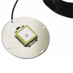 A-132 GPS Flange Antenna is a low profile GPS Flange Antenna with RF signal protection shield on the bottom and a 3-inch aluminum flange disk for strengthening the GPS signal reception. It is equipped with 3 signal noise filters and 2-stage LNA, which will provide the most accurate signal to GPS devices. Its strong signal reception and RF protection make A-132 GPS Flange Antenna suitable for customers who are looking to integrate or develop their own GPS product design. The antenna is designed for standard power input voltages ranging from 3V~6V with reverse polarity shutdown, over-current sense shutdown and EMC power line suppression. And, like all the other ARKNAV antennas, A-132 GPS Flange Antenna is made with high quality double-shielding cable and silver coated conducting pin, and meets RoHS directives.
A-132 GPS Active Antennas is the only innovating design antenna with performance, quality and a
Power protection circuit built-in to protect the active LNA’s, and most importantly the host GPS
receiver down the connector end from the danger of a SHORT circuit external antenna (Note: GPS
receiver front-end can be destroyed or de-graded by an external GPS antenna in an over-load or
short conditions. The A-132 is a low profile GPS active antennas system for the next generation
multi-purpose GPS mobile antenna products for Telematics, Fleet Management, Navigations and
AVL applications. This small print size of the antenna design does not reflect over-all performance,
since the antenna itself needs no ground plane aid to deliver the L1 band small signal carrier that
originates from the 24 orbiting USA satellites located thousands of miles over-head and with the
ground reception power sensitivity at over -130dB. The A-132 antenna is also design as a standard
power input voltages in range from +3Vdc to +6Vdc with reverse polarity shutdown, over-current
sense shutdown and an EMC power line suppression. The most important over-all design concept of
the A-132 GPS Active Antennas is the complete protections of the host sensitive GPS receiver
made from any manufacturer that it serve and can also be destroy or de-grade using an improper
design antenna
| General | |
| 2 Stages active LNA | |
| Dual Filters, (HPF & LPF(lump element)) | |
| +28dB gain | |
| Dielectric Patch antenna | |
| Low Noise Low drop-out, Linear Regulator | |
| GPS receiver short circuit protect | |
| Low Loss RG/174 Coax cable | |
| Aluminum Base/ PC+ Radome Plastic | |
| Performance | |
| Receiving Frequency | L1 Band(1575MHz) |
| Output Impedance | 50 ohms |
| Polarization’s | Right Hand Circular (RHC) |
| Bandwidth | 10dB Mhz @ -3dB point |
| VSWR | 1.5 Typical @ 1575MHz |
| Elev. Angle Coverage | 5~90 degree |
| Az. Bearing Coverage | 360 degree |
| Filtering | Dual(BPF <10 Mhz B/W, LPF @1576 MHz Stop-band @ 1585MHz) |
| Over-all Gain | 28dB (typical including 4dB cable loss & Filters) |
| Over-all NF | <1.8dB @fo, 2dB max. |
| LNA Characteristic | K=>1 Un-conditionally Stable |
| RF Insertions loss | K=>0.1dB, leakage power 100mW /1 watt input |
| Power Consumption | 11mA to 13mA (max) |
| Power Input Sensor | Reverse Polarity Short Circuit shutdown |
| Over-Current Sensor | Thermal Over-current shutdown >+150degreeC |
| Electrical | |
| Power Input | +3Vdc to + 6Vdc input, Auto Switching |
| Physical | |
| Dimensions | 31 x 24.5 x 7mm +/-0.5mm |
| Mount | Magnetic |
| Radome Color | Black |
| Coax Connector | BNC, SMA, SMB, MCX, MMCX, GT-5 |
| Coax Cable | RG-174U double shielded 5m, Low Loss 0.7dB/m |
| Environmental | |
| Operating Temperature | -30 to + 85 degree C |
| Storage | -40 to + 90 degree C Open Frame with 3” Flanges & RF shield |
| File Name | File Size | Time |
| A-132 ARKNAV-Datasheet | 825 KB | Sep 18th 2009 |